 NIXIE CLOCK DIY
5V USB Powered-IN-18 6-tube Clock DIY version (DIP40)
Assembly Instructions
V1.0
Notice:
For assembling this NIXIE KIT you need to have the skill of soldering DIP components.
We use a Hakko FX-888 Soldering Station (with CF2 Iron Head). We use 183℃(degree C)low melt temperature solder wire S60, 0.5mm(Dia.), Brand Almit.
And for most of the SMD components are big size and easy to be assembled,if you have a Hot air blower station,will help.
For how to solder the DIP components, we recommend:
https://www.hakko.com/english/tip_selection/type_bc_c.html
https://www.hakkousa.com/video/
Building it
Well, because of the circuit is block based and not very complicated, all you need to do is get all the components in the right position and make sure no short or no float before you plug the
power in. We will show the soldering steps blow.
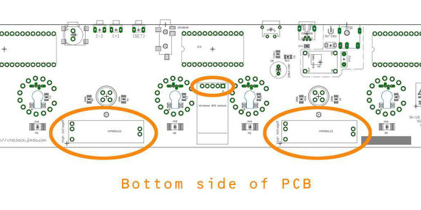
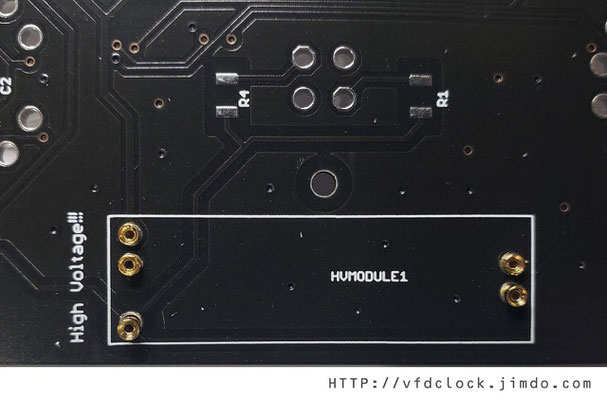
1): HV module Pins and WIFIGPS module PINS(Optional)
We need to solder some pins in this step,please solder it in this step,will be easier to be installed.
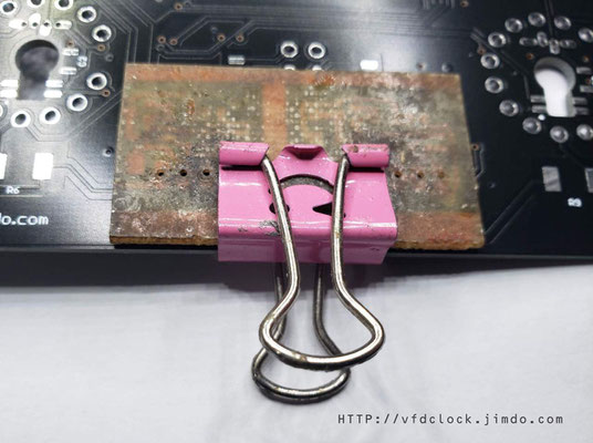
Please plug the Female PINs on the Bottom of the PCB then cover a had board like a small PCB or small
wood board etc.over the PINs, use two clamps to hold it with the main PCB, then flip the PCB. Now you can solder on the other side.
Tips: Because of the PINs are through hole version, please solder it carefully and do not let the tin goes in to the inside of the pins or will damage the PINs. If necessary, you can plug a
wood/bamboo toothpick in the bottom of PINs hole when soldering.


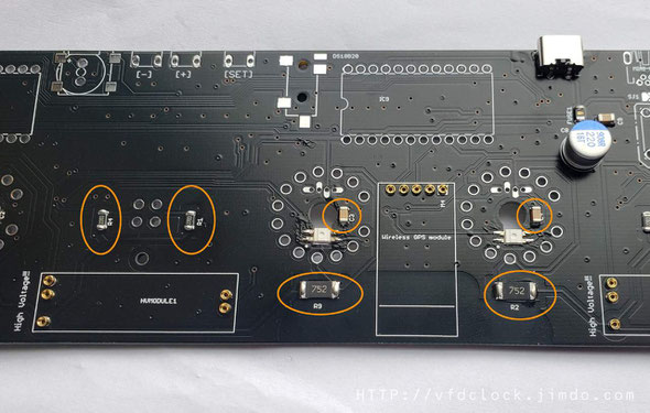
2): Solder the resistors and caps on the bottom side
The resistors are all in big side like 1206 or 2412,easy to be installed,and the caps for LED is in 1206 size.
For caps near LEDs,we recommend solder the caps first if you are using Hot air blower station,or the hot air may damage the LEDs.
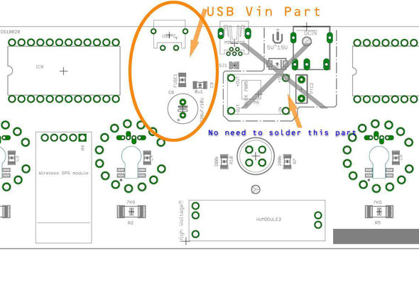
3): Install Main power and others components
The main power part has a USB socket(May in MINI USB/Micro USB/TYPE C,install only one USB socket),and a fuse, a 100nf cap and a Big Aluminum Electrolytic Capacitor(Please take care of it's direction).
No need to solder the 12V->5V buck convert part as shown on pic blow.(This part may not even exist in some of the PCBs, just Ignore it).

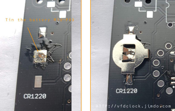
4): Install the CR1220 battery socket
In this part,we need to tin the middle battery pad first,then solder the metal holder,please do not add to much tin on the middle part.
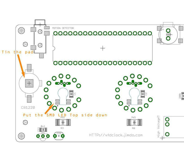
5): Solder all LEDS
May have two type of LEDS can be installed on PCB, one is smd version ,the other is dip version,would please install only one type of LEDS,do not install two types.
First ,we need to aware the first leg of LED,do not go wrong direction.
Second.LED is easy to be damaged when soldering,we need skills for low down its temperature.
For SMD version of LED,need to use a slim metal stuff to touch its soldering pad as a heat sink. We use a Solder paste scraper as heat sink,you can use utility knife instead if
you do not have one.
You can use tape to protect the IN-18 soldering holes on PCB when soldering the LEDs.


For soldering DIP version of LEDs,Use a bundle of copper wire to wrap around the pin a few rounds as
heat sink. Then plug the LED in the PCB and solder it,when done,remove the wire.


6): Solder all IC sockets
We need to install 3pcs of IC sockets,one is the main MCU module in DIP24 and the others are two DIP40 NIXIE driver module socket,please aware the direction of the sockets ,do not go invert.
We recommend u cut the thin legs of the socket before solder it on PCB as shown on the pics blow.


7): Solder Middle Colon Pins
The middle colon pins are on the top side of PCB,solder it a u solder the HV-module pins before.

8): IN-18 PINS
Now we are going to solder the IN-18 PINS.Please flip the PCB to the front side,the PINS need to be installed on this side and please solder it on the middle part of the PINs;
First we recommend you plug the PINS in the IN-18 legs,then plug ALL the PINS to the install holds,plug it down to the middle part, then flip the PCB ,solder the PINs on the bottom side of PCB;
!!!Plase double check to see if all PINs are plugged to the middle part before you solder the PINs!!!


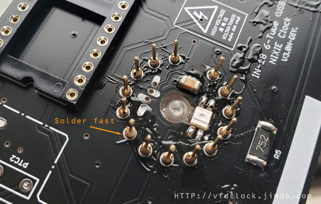
In soldering the PINS,if necessary,you need to keep pushing the tubes down to make sure all the PINS have been soldered on the middle part, please trade care of this part.
!!!Pleas note, do not add too much tin in soldering PINs,and please solder it fast. If add to much tin, the tin may go inside of the PINs and will solder the IN-18 tube legs with the socket,which will be big problem. We recommend add a little bit body lotion or oil on the surface of all in-18 PINs, will help to prevent be soldered together with socket.
Make A fast testing:
And after finished soldering on tube PINS,give it a power on test(*Remember to plug the MCU module and Driver Modules and HV mpdules in socket for testing) to see if have any problem.
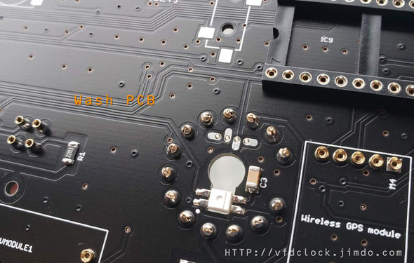
9): Cleaning the Circuit Board
You can use the household rubbing alcohol and a toothbrush to remove the solder flux on the PCB.
If available, the anhydrous alcohol (used for electronics cleaning) works much faster. Blot the cleaned area with a non-linting tissue (like Kimwipes EX-L) or a clean towel or you can do it in your own way.
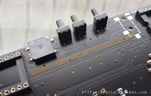
10): Buttons and Buzzer
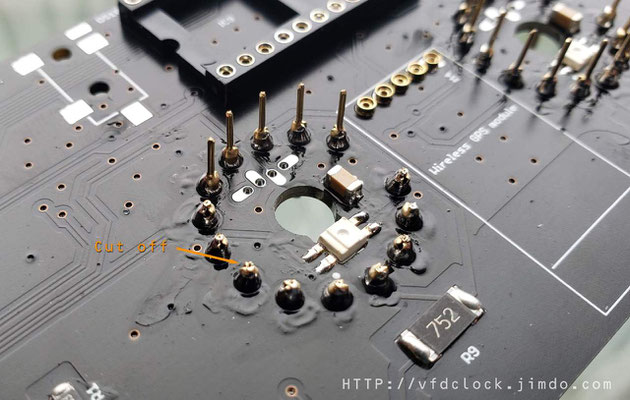
Because of Buttons and Buzzer etc. can not be washed, we need to solder 4pcs Keys and 1pcs Buzzer after cleaning the PCB. If the Buttons are one side two pins version,just solder it directly on PCB,if the Buttons are two side 4pins version,cut one side 2 pins off buy yourself,and band it flat the other side of 2pins then solder it and cut it short(or cut it short first before soldering);
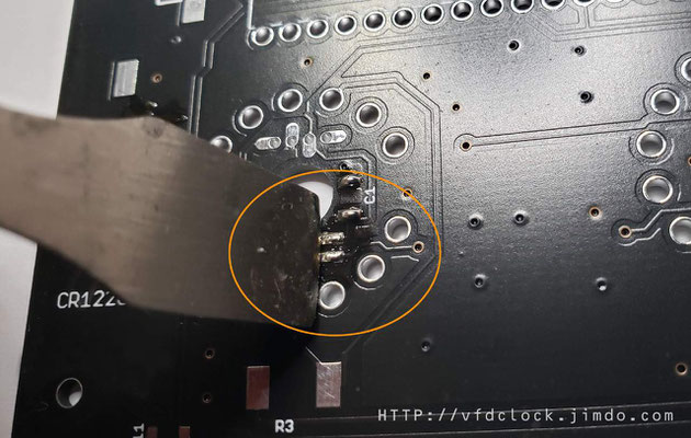
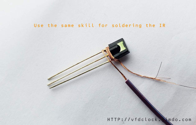
Extras :
The IR function is optional,you need to solder the IR sensor on PCB,use the same skill of soldering the DIP LED as shown in the pic.
And is also have WIFIGPS module,you can just plug the module in the middle-front side(bottom) of PCB .
For how to setting the WIFIGPS, please check:
If it has UART BPS menu ,please select :9600bps.

11): Create middle comma
For how to assembling the Middle comma,please visit:
KIT-Create the Middle Dot Comma for IN-18 NIXIE clock
You can make your own decision of the location of the bulbs in the middle glass tube.
The full map of the clock.


