 NIXIE CLOCK DIY

This is the 2.0 version of 3 tube NIXIE thermometer, in this version,we move the USB socket to the middle back of the PCB,and added an 3.5mm female socket and a button(to turn the LED ON/OFF).
The oC and oF version use the same source code by adding an C/F jumper on PCB.
(Short the [F] jumper to select the oF version,left it open to select the oC version.)
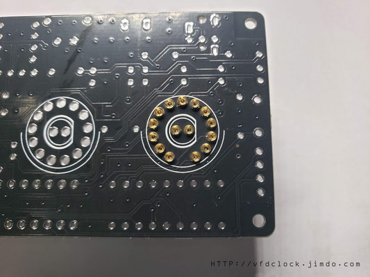


Solder the female through hole pins first.
1. plug the pins on the TOP side of PCB;
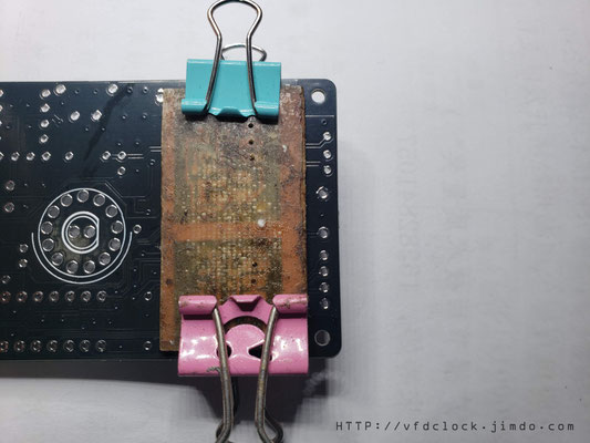
2. cover a PCB or hard board on the top of PINS and hole it on PCB by using foldback clip;
3.Flip the PCB then solder the female pins;
In this version,we added 2 middle female pins to install LEDs, you can replace the LEDs by yourself by hand.
We add orange color LEDs we customized from factory in default, its colors are very close to NIXIE color. If you wanna another colors of LED,you can replace it by yourself. Most of the std. 3mm and 5mm dia. round LEDs all fit with the socket.
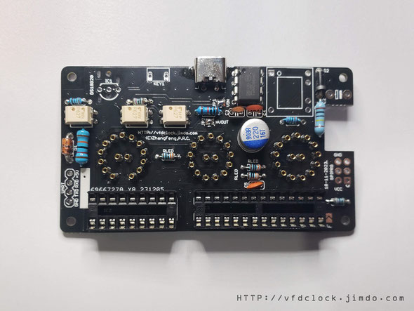
Solder the rest of the equipment on PCB as shown on the pic.
Aware the IC socket directions and remember to solder the VIN and HVout 2 jumpers.
In this new version,we add a jumper on the right-bottom of the PCB with MARK [F],if wanna display temperature in oC, left this jump open,if need to display in oF version,please short this jumper.
Do not solder the HV cap and transformer and 3.5mm audio socket and button,those equipment can not be washed.


The 2 pics be shown up are the PCB been washed. You can zoom the pics to compare with your PCB to see if all the equipment are be installed correctly.
When done, wash the PCB and make it dry.

When PCB be washed and dried,you can solder the transformer and button,.
for the DS18B20 Part,you can solder it on PCB directly,and if you wanna install it in a 3.5mm audio jack ,you can solder a 3.5mm audio audio socket on PCB.

For how to create a DS18B20 sensor in a 3.5mm audio jack,please visit:
Create a DS18B20 sensor in a 3.5mm audio jack
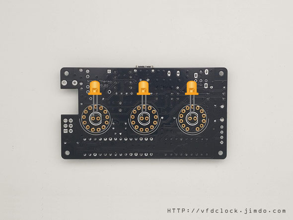
Plug the LED on the top side of the PCB.
For LED part,recommend cut the legs short first,and aware the LED [+]leg and [-] leg.

Then plug the nixie tubes in the socket.
For oC version,you need to prepare:
2pcs IN14+1pcs [IN19A ИН-19A] NIXIE tubes;
For oF version ,you need to prepare:
2pcs IN14+1pcs [IN19B ИН-19Б] NIXIE tubes;
When done,Plug 3.5mm audio jack DS18B20 Sensor in the socket, then plug USB power, if all fine,the NIXIE tubes will display the temperature data after ~2 seconds.
Assemble the Acrylic enclosure
In editing.............
